|
| | 
Induction
magnetometer LEMI-606 for RESONANCE experiment
RESONANCE experiment focuses
on the study of the processes in the inner magnetosphere of our planet. The
objectives of the project include the investigation of interactions between
waves and particles, and monitoring of the large-scale changes in the
magnetosphere associated with geomagnetic activity and magnetic storms.
Magnetic field fluctuations will be measured by four tree-component
induction coil magnetometers LEMI-606 which will installed on two pairs of
satellites will be launched on a specially designed path - the so-called "magnetosynchronous
orbits." It is known that the plasma parameters vary rapidly in space and
time, so in the case of simultaneous measurements at four points high
temporal resolution and low measurement error must be provided.
Because of that high demands on the possible identity of the parameters of
devices that are on all four satellites are placed.
Three-component induction coil magnetometer LEMI-606 is intended for the
study of magnetic field fluctuations in space conditions in the frequency
band 1-20000 Hz. It is intended to be used as input sensor of
Electromagnetic Wave Analyzer (ELMAVAN). |
|
 |
|
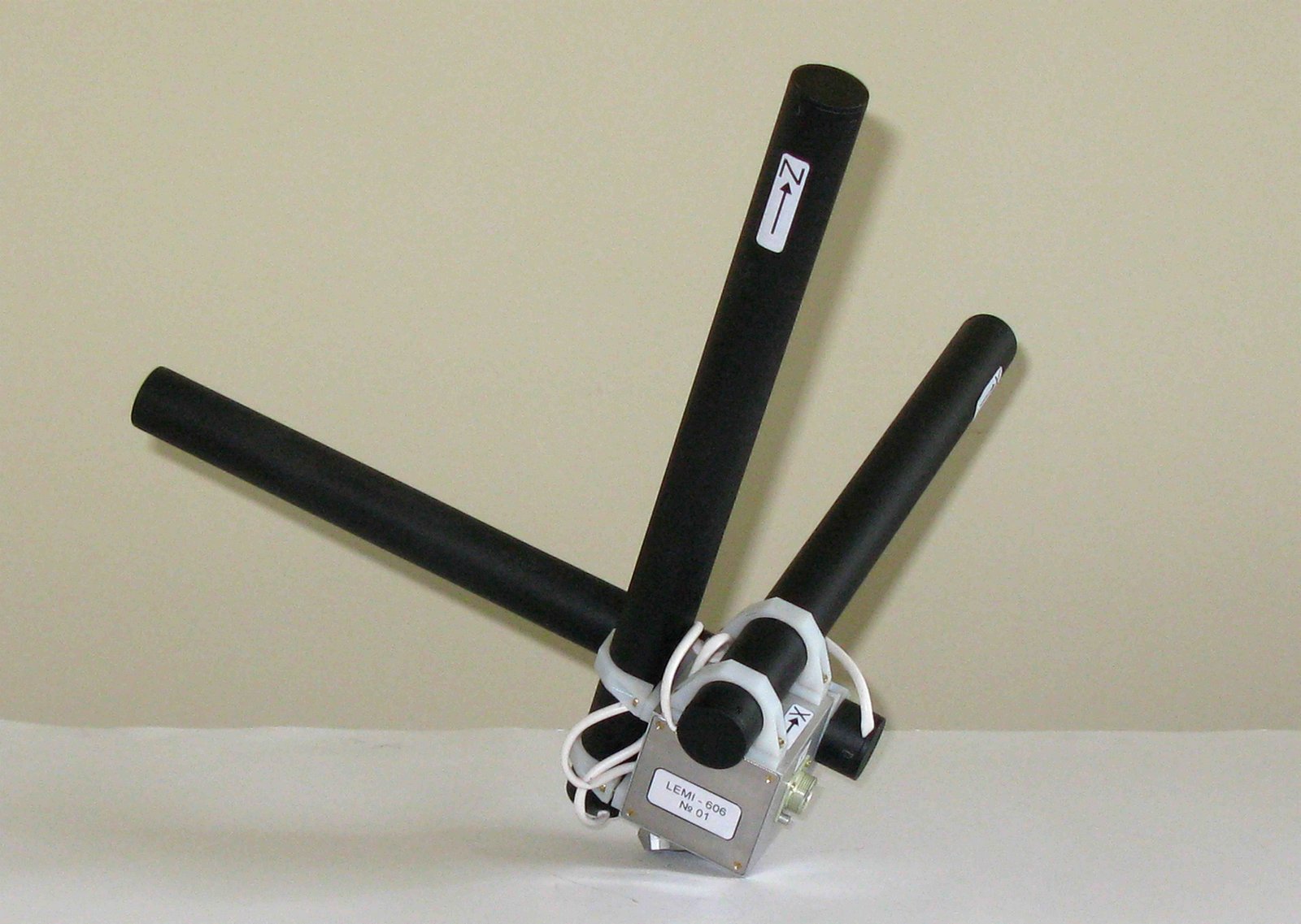
Each component of induction
coil magnetometer LEMI-606 consists of induction coil sensor (ICS) and
preamplifier, both located inside the same protective housing – black tube
at the photo.
ICS consists of magnetic core, main winding and feedback winding.
The original peculiarity of the ICS magnetic core construction is that it is
made of a number of longitudinal convex-shaped ferromagnetic high
permeability amorphous tapes insulated one from another. In such a way the
magnetic core forms a hollow tube that allows placing the preamplifier
inside it. The main winding is wound on this core. This construction first,
allows considerable weight decreasing and second, helps to protect
additionally the preamplifier against the radiation what is especially
important for RESONANCE experiment.
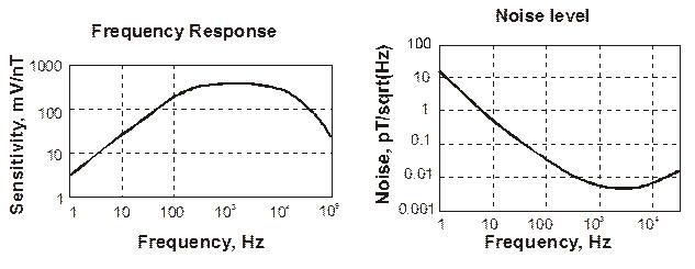
Output signal of main winding is coupled to ultra low-noise input
preamplifier with local feed-back, the output of which is coupled to the
magnetic flux feedback winding through the correction circuit. Magnetic and
local feedback circuits form the flat part of the magnetometer transfer
function within frequency band 100 – 20000 Hz; in the frequency band 1-100
Hz the output signal is proportional to the signal frequency.
There is also an additional high-frequency correction circuit inside
preamplifier which serves to ensure the stable operation of all the system
“ICS - preamplifier” in full frequency band. The counter-phase output signal
to form the symmetric output for additional decreasing of interferences is
provided by the output inverter.
The small box to which all three components of the induction magnetometer
are fixed serves for the magnetometer fixation to the boom and contains
power supply and communication boards. These units provide power voltage
stabilization and transfer of magnetometer output signals to the ELMAVAN.
The main parameters of LEMI-606 are given below.
|
TECHNICAL
SPECIFICATIONS
| Full frequency band of
received signal, Hz |
1 … 20000 |
| Flat part of
transfer function in the pass band, Hz |
100 … 20000 |
| Transformation factor at
flat part and at differential output, mV/nT |
40 |
Magnetic noise level, pT×Hz^(-1/2):
at 1 Hz
at 100 Hz
at 1 kHz
at 10 kHz |
20
0.05
0.006
0.008 |
| Power supply voltage |
± 5 V |
| Power consumption, mW |
110 |
| Outer dimensions (one
component), mm |
l = 360, d=30 |
|
The conditions of the
magnetometer installation onboard the satellite platform constrain
non-symmetric construction of the magnetometer. This imposes additional
problem with mutual influence of the components and their orthogonality.
Because of this the calibration of the LEMI-606 must be executed in the
assembled structure only, what creates serious problems to find the
convenient calibration facility. Between all known ones it seems that the
Calibration stand at Garchy, France, is the only place where the parameters
of this magnetometer may be checked in all operation frequency range. These
tests were made with flight model and showed satisfactory parameters.
 |


|
